



ABOUT ME

Hi, I’m
Kleber Molina.

A mechatronics engineering student currently based in Zittau, Germany. I enjoy combining electronics, mechanical design and software to build practical mechatronic systems.

I am currently looking for a mandatory internship from March 2027.

German–Mexican double degree in Mechatronics Engineering at Tecnológico de Monterrey and Hochschule Zittau/Görlitz.

Spanish (native) · English (C1) · German (A2)

Portrait of Kleber Molina

Below are some of the projects and professional experiences I found most challenging and learned the most from. I hope you find them as interesting as I did. If you have questions or would like more information, feel free to contact me.

Get in touch

02

Experience

  1. May 2025 — May 2026John Deere logo
    John Deere internship badge

    John Deere

    Virtual Systems Analysis Intern · Power Systems — Methods & Tools

    I developed and updated full-engine simulation models in GT-SUITE, covering EGR, intake, cylinder head, charge-air cooling, high- and low-pressure turbochargers and exhaust systems, and validated them against measured engine data.

    I converted engine-specific subsystems into shared, configurable modules, reducing model duplication across configurations. I also built MATLAB automation for PID tuning of simulated dynamometer models, and MATLAB and Python tools for evaluating BSFC and PMEP.

    I developed and updated full-engine simulation models in GT-SUITE, supporting engineering teams working on controls, validation, and engine performance. My work covered EGR, intake, cylinder head, charge-air cooling, high- and low-pressure turbochargers, and exhaust systems. I validated simulation results against measured engine data to check that model updates accurately represented engine behavior.

    I converted engine-specific subsystems into shared, configurable modules. Instead of maintaining separate versions of similar components, I structured the models to reduce duplication and make updates easier to share across engine configurations. I checked the revised modules against previous results and measured data to ensure the changes preserved their behavior.

    I worked and developed various MATLAB and Python tools for improving and automating processes, extracting data and facilitating day-to-day engineering work. This included automation for PID tuning of simulated dynamometer models and tools for evaluating brake-specific fuel consumption (BSFC) and pumping mean effective pressure (PMEP).

    The models and tools supported broader Virtual Systems Analysis workflows aimed at reducing reliance on physical engine test-cell testing. I worked directly with model users across teams, responding to requests and implementing changes to support their analysis needs.

    GT-SUITEMATLABPythonEngine simulationModels from measured dataPID tuning
  2. Aug 2023 — Feb 2025VANTTEC logo

    VANTTEC

    Electronics & Embedded Systems · Member → Team Leader

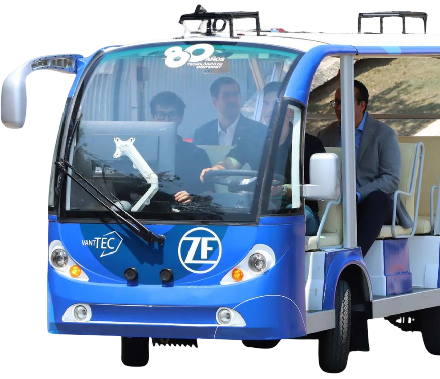
    I developed electronics for a golf cart being converted into an autonomous vehicle with LiDAR and cameras, and later led a team of four.

    In KiCad, I revised and routed two PCBs, a general-control board and a stepper-interface board, adding Molex connectors for easier maintenance. I assembled, soldered and tested them within the vehicle’s STM32 and CAN system.

    I developed electronics for a golf cart being converted into an autonomous vehicle equipped with LiDAR and cameras. During my time at VANTTEC, I progressed from team member to Electronics and Embedded Systems Team Leader, leading four members and coordinating work with other vehicle development teams.

    My main technical contribution was updating two PCBs: a general-control board and a stepper-interface board. Using KiCad, I revised schematics, routed the boards, and integrated Molex connectors to improve wiring between modules and make maintenance easier. I also assembled, soldered, and tested the manufactured boards, verifying their operation within the vehicle’s STM32 and CAN communication system.

    Alongside PCB development, I integrated additional sensors and indicators requested by other teams and diagnosed and repaired electrical faults. As team leader, I assigned tasks and recruited new members before handing over my responsibilities.

    Tools & technologies: KiCad · STM32 · CAN · PCB design and assembly · Soldering · Hardware testing · Vehicle integration

    VANTTEC stepper-interface PCB · Interactive 3D view

    VANTTEC autonomous vehicle platform

    Interactive 3D stepper module · drag to orbit · scroll or pinch to zoom

    KiCadSTM32CAN

01

Projects

PROJECT 01 7TH SEMESTER · PCB DESIGN · AUTOMOTIVE TESTING

ECU power management
& testing system

The main goal set by International Motors Mexico was to create a system that controls power to four ECUs, monitors their CAN messages and electrical behaviour, and runs automated tests.

I was responsible for the circuit design, PCB layout, component calculations, assembly and soldering: one replaceable board per ECU, with MOSFET switching for fast, repeated operation without contact wear. The project was selected for ExpoIngenierías and demonstrated live with International ECUs.

Validation included extended operation, repeated switching, CAN reception from real ECUs and sensor readings checked against lab instruments. I used an oscilloscope to measure switching response times. Safety features included a main fuse, shutdown on over-voltage and a fail-safe if the computer disconnected. Hardware and documentation were handed over to International. Due to their confidentiality policy, ECU-specific CAN messages, VISA command sequences and detailed test results cannot be shown. ExpoIngenierías certificate ↗

During my seventh semester, I worked with International Motors Mexico on a system for controlling power to four ECUs, monitoring their CAN messages and electrical behaviour, and running automated tests. Weekly meetings with two International engineers helped guide the development through progress reviews and technical feedback. The prototype used one replaceable board per ECU, with independent control of its battery, accessory and ignition lines.

I was responsible for the circuit design, PCB layout, component calculations, assembly and soldering. I calculated resistor values and PCB trace widths, selected protective components, and chose MOSFET switching to support fast, repeated operation without mechanical contact wear. I also integrated measurement sensors and output-status LEDs. The system combined ESP32 firmware written in MicroPython with a Python computer interface developed mainly by my teammates.

A tight budget, without university funding, shaped the hardware choices. The prototype used through-hole components and separate modules for CAN communication and current and voltage sensing. I also proposed a smaller, integrated PCB combining the ESP32, CAN circuitry and measurement chips on one board. This alternative remained a design for future development and was not manufactured.

A major part of my work involved thinking through possible failure scenarios and testing the system’s response. Validation included extended operation, repeated switching, receiving CAN messages from real ECUs, and checking sensor readings against laboratory instruments. I used an oscilloscope to measure switching response times. The system also supported text-based test sequences, a main fuse, shutdown when monitored voltage exceeded a set limit, and a fail-safe response if the computer disconnected. Improvements to wiring, connectors and future expansion were documented for later versions.

The project was selected for ExpoIngenías, where it was demonstrated live using International ECUs and received positive feedback from professors and judges. The hardware and documentation were handed over to International, whose engineers expressed interest in continuing its development.

Tools used: KiCad · ESP32 · Python / MicroPython · CAN communication · VISA communication · PCB assembly and soldering · Oscilloscope · Hardware validation

Due to International’s confidentiality policy, ECU-specific CAN messages, VISA command sequences, and detailed test procedures and results involving various ECUs cannot be shared or shown here.

I handled the circuit design, PCB layout, component calculations, assembly and soldering. The system used MOSFET switching, an ESP32 running MicroPython, current and voltage sensing, status LEDs, and a Python interface. I also designed 3D-printed cases to keep the modules organized and make the system more modular. I validated the system with real ECUs provided by International.

Throughout the project, we received constant feedback from the company during progress reviews and technical discussions. The project was selected for ExpoIngenías and demonstrated live. At the end, we handed over the hardware, documentation and project files so the company could continue developing the system. Because of International’s confidentiality policy, ECU-specific CAN messages, VISA command sequences and detailed test procedures cannot be shown.
KiCadESP32 / MicroPythonCANVISAOscilloscope

PROJECT 02 6TH SEMESTER · INDUSTRIAL ROBOTICS · PLC · HMI

Robotic assembly station
— MIT FrED Factory

I led a four-person team rebuilding Station 3 of the MIT FrED Factory line. The station used a KUKA robot to assemble part of a filament extrusion device.

With the previous PLC programs unavailable, I corrected the KUKA interface wiring, replaced the Siemens + Allen-Bradley arrangement with one Siemens PLC in ladder logic, rewrote the robot sequence from scratch and developed the HMI.

Without the usual robot programming software, I wrote the operating logic directly as code from recorded positions. The HMI shows process progress, timers, robot status, sensor states and missing-part warnings, with door interlocks and robot-status checks. The handover included schematics, TIA Portal files and operating documentation.

In the same course, a small project with Schneider Electric Mexico won a participant-voted award. LinkedIn post ↗

I led a four-person team rebuilding Station 3 of the MIT FrED Factory production line, which assembled part of a filament extrusion device. The station used a KUKA industrial robot to handle and press together the funnel assembly. With the previous PLC programs unavailable, unreliable wiring and recurring alignment problems, I focused on rebuilding the controls and improving consistent operation. The updated station reduced assembly time from approximately 3 minutes to 2 minutes 45 seconds per part.

My main responsibilities covered control-system integration, electrical rewiring, PLC programming, robot sequence logic and HMI development. I corrected the KUKA interface wiring and signal assignments, allowing the original Siemens and Allen-Bradley arrangement to be replaced by one Siemens PLC programmed in ladder logic using TIA Portal. I rebuilt cable connections, sized wiring to suit the station and improved the robot interface connection.

The robot sequence was rebuilt from scratch around the updated fixtures. With the usual robot programming software unavailable, I wrote the operating logic directly as code, using recorded robot positions and manually transferring the programs to the controller. Updated paths, speeds and intermediate positions improved pickup, placement and pressing movements. The station also incorporated alignment guides, a redesigned 3D-printed gripper and gravity-fed part storage with sensors for stock and base detection.

I developed an HMI showing process progress, timers, robot status, sensor states and missing-part warnings. Start, stop and continue controls supported operation, while selected routines could be reset without restarting the entire assembly sequence. Door interlocks and robot-status checks prevented operation when the required conditions were not met.

The final handover included electrical schematics, TIA Portal files and operating documentation to help future students maintain and extend the station.

Tools used: Siemens PLC · TIA Portal · Ladder logic · KUKA robot programming · HMI development · Electrical integration · Sensors and interlocks · Process validation

Fun fact: In the same course, I worked on a small project with Schneider Electric Mexico, simulating a circuit-breaker stamping process through robot movements and MDF fixtures. Although it was relatively simple, it won a participant-voted award, earning prize kits and a LinkedIn feature. LinkedIn post ↗

The station had unreliable controls, unavailable PLC programs and recurring alignment problems. We rebuilt the controls and improved the station’s reliability, reducing assembly time from approximately 3 minutes to 2 minutes 45 seconds per part.

I corrected the KUKA wiring, replaced the previous Siemens and Allen-Bradley arrangement with one Siemens PLC programmed in ladder logic using TIA Portal, and rewrote the robot sequence from recorded positions. I also developed the HMI for process progress, timers, robot status, sensor states, missing-part warnings and safe operation.

The work included improved fixtures, a redesigned 3D-printed gripper, gravity-fed part storage, sensors and safety interlocks. I handed over the schematics, TIA Portal files and operating documentation.

Related Robotics Challenge

During the same period, I also worked in the laboratory on a small Schneider Electric Mexico project that simulated a circuit-breaker stamping process using robot movements and MDF fixtures. It won a participant-voted award and was featured on LinkedIn ↗.

Siemens PLCTIA PortalKUKAHMI

PROJECT 03 RESEARCH COLLABORATION

Embedded vision &
robot control platform

A tracked robot built for a master’s research project on TinyML-based path following. I developed the hardware and software infrastructure for testing future models.

I adapted a Madgwick sensor-fusion implementation for the MPU9250 with DMA-based IMU acquisition, and implemented encoder acquisition and PI motor control. On the Raspberry Pi I integrated a camera with OpenCV and a local web interface, packaged with Docker.

A control engineering professor invited me to develop a robotic platform for a master’s research project on TinyML-based path following. My task was to build the hardware and software infrastructure needed to test future models. I developed a tracked, differential-drive robot using an STM32 NUCLEO-F446RE and Raspberry Pi 5, combining motion control, orientation sensing, camera capture and a browser-based interface.

I adapted an existing Madgwick sensor-fusion implementation for the MPU9250 and implemented DMA-based IMU acquisition to reduce the processor’s involvement in data transfers. I reused and refined my earlier calibration routine, corrected sensor readings and applied filtering to reduce noise and orientation drift. I also handled wheel-encoder acquisition, implemented PI motor control, and added fail-safe behaviour.

On the Raspberry Pi, I integrated a Pi Camera and OpenCV, adjusting image resolution, frame rate and noise reduction while preserving the colour information required by the planned models. I built a local-network web interface that displayed live video and IMU readings, alongside buttons for testing the robot’s movement from a phone or computer.

I packaged the Raspberry Pi applications and their dependencies using Docker, allowing the software stack to launch with one command and making the setup easier to reproduce and restart. At handover, sensing, video streaming, browser controls and robot movement were working. The platform was prepared for the master’s student’s next stage of model integration; developing and deploying those models was outside my contribution.

Tools used: STM32 NUCLEO-F446RE · Raspberry Pi 5 · MPU9250 · Madgwick sensor fusion · DMA · Encoders · PI control · L298N · Pi Camera · OpenCV · Docker

A control engineering professor invited me to build a tracked, differential-drive platform for a master’s research project on TinyML-based path following. I developed the hardware and software infrastructure needed to test future models using an STM32 NUCLEO-F446RE and Raspberry Pi 5.

I implemented orientation sensing with the MPU9250 and Madgwick sensor fusion, DMA-based IMU acquisition, wheel-encoder handling, PI motor control and fail-safe behaviour. On the Raspberry Pi, I integrated a Pi Camera with OpenCV and built a local web interface for live video, IMU readings and movement testing.

I packaged the software stack with Docker so it could be launched and reproduced more easily. At handover, sensing, video streaming, browser controls and robot movement were working; integrating and deploying the future TinyML models was outside my contribution.

STM32 NUCLEO-F446RERaspberry Pi 5OpenCVDocker
Transparent cutout of the John Deere tractor-inspired robot

PROJECT 04 5TH SEMESTER · EMBEDDED · MOTOR CONTROL

Autonomous
tractor-inspired robot

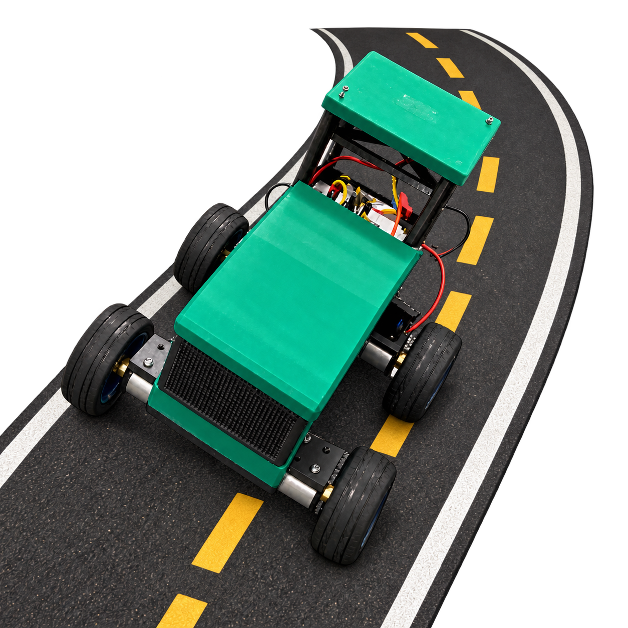
Control software and electronics for a robot that drives a square route over rough, gapped tiles and returns to its start point, guided by John Deere engineers.

Using an STM32, I implemented PI speed control with four wheel encoders and a PID heading controller. I modelled the motors with PRBS test inputs, tuned the controllers in MATLAB and wrote an MPU9250 calibration routine.

I developed the control software and integrated the electronics for a tractor-inspired robot during my 5th-semester Industrial Automation course, under the guidance of John Deere engineers. The challenge was to follow a square route of approximately 15 m per side across rough tiles with gaps, then return to the starting point and direction. The robot met the required 15–30 cm return tolerance. I focused on reliable movement and automatic heading correction rather than speed.

Using an STM32F103C8T6, I implemented PI speed control with feedback from four wheel encoders and a PID controller to correct the robot’s heading after disturbances. I used PRBS test inputs to record the motors’ response, build a plant model, and check it against separate data. I then used MATLAB’s PID tuning tools to tune the PI control.

I developed a calibration routine for the MPU9250 that included keeping the robot still and rotating it in figure-eight movements. I corrected the raw sensor readings, applied low-pass filtering, and adjusted sensor weights between straight sections and turns. Gyroscope and magnetometer readings supported heading control, while acceleration and encoder data helped estimate travel distance.

I also made molds and cast silicone wheels to improve grip and reduce bouncing. The robot used a laser-cut acrylic base, a 3D-printed tractor-style body, L298N motor drivers and rechargeable 18650 batteries, with separate supplies for the control electronics and motors. I tested and refined the system on the course surface, including its ability to straighten its heading after being pushed.

Tools used: STM32 · C · MPU9250 · MATLAB · System identification · PRBS · PI/PID control · Encoders · L298N · Silicone molding

I developed the control software and integrated the electronics for a tractor-inspired robot during my 5th-semester Industrial Automation course, guided by John Deere engineers. The challenge was to drive a square route of approximately 15 m per side across rough tiles with gaps, then return to the starting point and direction within a 15–30 cm tolerance.

Using an STM32F103C8T6, I implemented PI speed control with four wheel encoders and PID heading correction. I used PRBS test inputs and MATLAB to model the motors and tune the controllers, and developed an MPU9250 calibration and filtering routine to support reliable heading and distance estimation.

I also designed and tested silicone wheels, a laser-cut acrylic base and a 3D-printed tractor-style body, with L298N motor drivers and separate power supplies for the control electronics and motors. The robot returned within the required tolerance and received a 10/10 project grade.

STM32 / CMATLABPI / PIDSensor fusion

PROJECT 05 4TH SEMESTER · MECHANICAL DESIGN · MOTION CONTROL

Mini mechatronic
foosball table

I designed and built a mini foosball robot during my 4th-semester Implementation of Mechatronic Systems course, finishing second out of more than 15 designs in the class tournament.

My custom gear system moved the player faster than direct-drive stepper designs, and a 12 V solenoid let the robot move and strike at the same time. I designed the CAD parts and MDF case, and built a joystick controller, goal counter, LCD scoreboard and a custom AC–DC power supply.

My custom gear system achieved faster player movement than direct-drive stepper designs, while a PI controller made movement smoother. I used a constant PWM signal from the Arduino's hardware timer to control the stepper motor through a TMC2209 driver, allowing the robot to move and strike at the same time using a 12 V solenoid.

I designed the mechanical parts in CAD, printed them in PLA, and designed and cut the MDF case. I also built a handheld controller with a joystick and shooting button, added a distance sensor to count goals, and used a 16x2 LCD to display the score and game information. Two limit switches kept the player within its travel range. I tested and refined movement, shooting and goal detection by adjusting the hardware and code.

For extra credit, I designed and built an AC-DC power supply with a 12 V output and a step-down converter to 5 V. Its extra power capacity allowed me to reuse it in later projects.

Tools used: Arduino Uno · CAD · 3D printing · MDF fabrication · Gear design · PI control · Power electronics

The project was inspired by the Automated Foosball Table concept and included my own design and component choices.

The robot used a custom gear system for faster player movement than direct-drive stepper designs. A PI controller improved the motion, while a timed, modified PWM signal controlled motor movement through the TMC2209 driver. This timing allowed the robot to drive and shoot at the same time, with the 12 V solenoid performing the strike.

I designed the mechanical parts in CAD, printed them in PLA and designed and cut the MDF case. I also built a joystick controller with a shooting button, a distance sensor for goal detection, a 16×2 LCD scoreboard and limit switches to keep the player within its travel range.

For extra credit, I designed and built an AC–DC power supply with a 12 V output and a step-down converter to 5 V. The project finished second out of more than 15 designs in the class tournament.

ArduinoGear designPI control3D printing

PROJECT 06 MEASUREMENT · SIGNAL ANALYSIS

AC frequency
measurement system

Arduino · Python · Signal Analysis · Mechanical Design

I designed and built this AC frequency measurement system for my Mechatronic Integration course, combining Arduino, Python and mechanical design for power-supply monitoring.

The system monitored frequency changes around the expected 60 Hz value as electrical loads were added or removed. A small display showed the readings, while LED indicators warned when the frequency crossed set thresholds.

The Arduino collects 800 readings per batch and sends them to Python over serial communication. Using NumPy and the Fast Fourier Transform (FFT), I analysed the signal’s frequency content and calculated a frequency estimate, then built a live Matplotlib display to track changes across successive measurements.

For the mechanical side, I designed an MDF case in SolidWorks to support 100 kg while staying within a weight limit. Structural analysis helped identify weak points, and an informal load test supported two adults with a combined weight of approximately 220 kg without failure.

Tools used: Arduino · ACS712 · Python · NumPy · Matplotlib · FFT · Serial communication · Display and LED indicators · SolidWorks · MDF fabrication

The Arduino collected 800 readings per batch and sent them to Python over serial communication. Using NumPy and the Fast Fourier Transform (FFT), I calculated a frequency estimate and built a live Matplotlib display. I also designed an MDF case in SolidWorks to support 100 kg; structural analysis identified weak points, and an informal load test supported two adults weighing approximately 220 kg in total.

Tools used: Arduino · ACS712 · Python · NumPy · Matplotlib · FFT · Serial communication · Display and LED indicators · SolidWorks · MDF fabrication

ArduinoACS712Python / NumPyFFTMatplotlibSolidWorksMDF fabrication

03

Contact

kleber.molinayepez@gmail.com